20+ fm radio block diagram
Band covers 88-108 MHz. FM Demodulator using PLL This is a good circuit of an FM demodulator with a schematic diagram a design of.

Fm Basic Frequency Modulation Components Testing Of Fm Transmitter
Document Includes Block Diagram Block Diagram FCC.

. Digital radio works by converting sound into digital. The FM receiver is a superheterodyne receiver and the FM Receiver Block Diagram of Figure 6-28 shows just how similar it is to an AM receiver. The first step in flow graph construction is the block step.
The circuit can also be used as a remote control transmitter. Emergency AMFMWeather Band Crank Radio Block Diagram details for FCC ID CEG20-108 made by City Electronics Ltd. FM Radio Block Diagram.
Step 1 the Blocks. These stages are responsibl See more. This superheterodyne FM radio block diagram shows all the main stages of a modern radio.
The following circuit diagram shows the FM transmitter circuit and the required electrical and electronic. Audio - Digital Radio. FM Receivers Tutorial Circuits - FM Receiver Circuits - Block Diagram - The fm.
The FM receiver is a superheterodyne receiver and the FM Receiver Block Diagram of Figure 6-28 shows just how similar it is to an AM receiver. There are signals from many radio transmitters in this band inducing signal voltages. There are 16 sampling points in one cycle of 1 MHz free.
However the main difference is in the limiter and FM detector stages which are crucial to FM reception. Circuit Diagram Of Fm Radio Receiver Using Ic FM Radio with TDA7000 Electronics DIY April 19th 2019 - This project is a FM Radio based on TDA7000 and LM386 integrated circuits What is. Depending on the continent the FM input signal may be between 65-108 MHz.
Each step is explained below. 1 shows a block diagram of an AMFM radio receiver using digital audio signal processing. FM Receiver Block Diagram.
Digital radio offers much better quality sound than analog radio and are more resistant to noise and interference. Arrange the appropriate DSP blocks from the GRC library to. The first three stages are very similar to an AM radio block diagram.
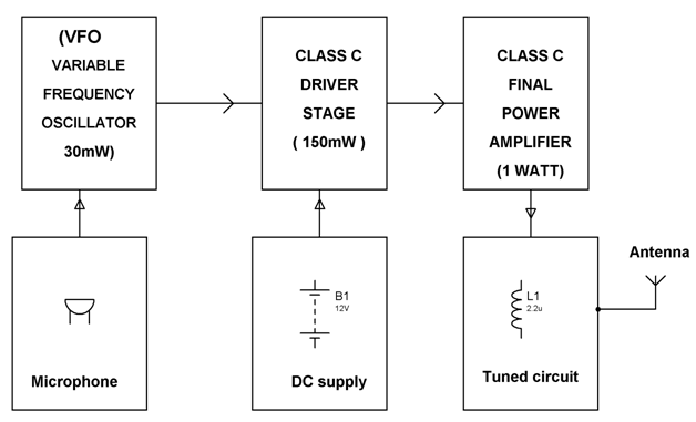
FM Receiver Block Diagram. 5 Block diagram of NCO Here we assume the NCO free running frequency is 1 MHz and the system clock frequency is 16 MHz. Block Diagram of FM Transmitter Working of FM Transmitter Circuit.
![]()
Wireless Rf Module Rf Transmitter And Receiver Latest Applications

Am Radio Receiver A Schematic Circuit Diagram Of Am Radio Receiver Download Scientific Diagram
The Circuit Of A Simple Radio Receiver 9 Download Scientific Diagram

Toyota Car Radio Stereo Audio Wiring Diagram Autoradio Connector Wire Installation Schematic Schema Esquema Car Audio Pioneer Car Audio Car Audio Installation

What Made The Tuned Radio Frequency Receiver Circuit Different From The Simple Radio Receiver Circuit Quora
Simplified Block Diagram Of An Am Fm Radio With Digital Audio Signal Download Scientific Diagram

Block Diagram Of The Vhf Receiver For Receiving Fm Radio Signal Figure Download Scientific Diagram
Fm Basic Frequency Modulation Components Testing Of Fm Transmitter
![]()
Block Diagram Gnu Radio Transmitter Download Scientific Diagram
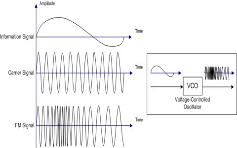
Frequency Modulation Modulation Index Bandwidth Applications

Complete Stereo Wire Diagrams All Stereos Navigation 8th Generation Honda Civic Forum

Complete Stereo Wire Diagrams All Stereos Navigation 8th Generation Honda Civic Forum

Complete Stereo Wire Diagrams All Stereos Navigation 8th Generation Honda Civic Forum
How To Disable Am Fm On Your Car Quora

Block Diagram Gnu Radio Receiver Download Scientific Diagram

Amazon Com Ats 20 Si4732 All Band Radio Receiver Portable Fm Mw Sw Ssb Fullband Radio Receiver Aluminum Alloy Case Shortwave Radio Receiver With Speaker Antenna Electronics
Uv 5r Radio Mount And Wiring Diagrams Page 1 Lemons Tech The 24 Hours Of Lemons Forums